6.1 Impulse Drive
Describes the fusion-powered impulse propulsion system, its fuel supply, engine configuration and components, and the software-driven impulse engine control.
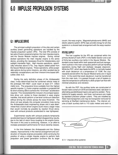
The principal sublight propulsion of the ship and certain auxiliary power generating operations are handled by the impulse propulsion system (IPS). The total IPS consists of two sets of fusion-powered engines: the main impulse engine, and the Saucer Module impulse engines. During normal docked operations the main impulse engine is the active device, providing the necessary thrust for interplanetary and sublight interstellar flight. High impulse operations, specifically velocities above 0.75c, may require added power from the Saucer Module engines. These operations, while acceptable options during some missions, are often avoided due to relativistic considerations and their inherent time-based difficulties (See: 6.2).
During the early definition phase of the Ambassador class, it was determined that the combined vehicle mass of the prototype NX-10521 could reach at least 3.71 million metric tons. The propulsive force available from the highest specific-impulse (Is) fusion engines available or projected fell far short of being able to achieve the 10 km/sec2 acceleration required. This necessitated the inclusion of a compact spacetime driver coil, similar to those standard in warp engine nacelles, that would perform a low-level continuum distortion without driving the vehicle across the warp threshold. The driver coil was already into computer simulation trials during the Ambassador class engineering phase and it was determined that a fusion-driven engine could move a larger mass than would normally be possible by reaction thrust alone, even with exhaust products accelerated to near lightspeed.
Experimental results with exhaust products temporarily accelerated beyond lightspeed yielded disappointing results, due to the lack of return force coupling to the engine frame. The work in this area is continuing, however, in an effort to increase powerplant performance for future starship classes.
In the time between the Ambassador and the Galaxy classes, improvements in the internal arrangement and construction of impulse engines proceeded, while continuing the practice of using a single impulse engine to perform both propulsion and power generation functions like its larger cousin, the warp engine. Magnetohydrodynamic (MHD) and electro plasma system (EPS) taps provide energy for all ship systems in a shared load arrangement with the warp reaction core.
IPS Fuel Supply
The fuel supplies for the IPS are contained within the primary deuterium tank (PDT) in the Battle Section and a set of thirty-two auxiliary cryo tanks in the Saucer Module. Redundant cross-feeds within both spacecraft and fuel management routines in the main computers perform all fuel handling operations during flight and starbase resupply stopovers. While the PDT, which also feeds the WPS, is normally loaded with slush deuterium at a temperature of 13.8K, the cryo reactants stored within the Saucer Module tanks are in liquid form. In the event that slush deuterium must be transferred from the main tank, it is passed through a set of heaters to raise the temperature sufficiently to allow proper fuel flow with minimal turbulence and vibration.
As with the PDT, the auxiliary tanks are constructed of forced-matrix cortanium 2378 and stainless steel, laid down in alternating parallel/biased layers and gamma-welded. Penetrations for supply vessels, vent lines, and sensors are made by standard precision phaser cutters. They are installed by Fleet Yard transporters and may be transporter-removed for servicing at Starfleet maintenance docks. The internal volume of each auxiliary tank is 113 cubic meters and each is capable of storing a total of 9.3 metric tonnes of liquid deuterium.
Emergency flight rules allow for the injection of minute amounts of antimatter into the impulse reaction chamber in the event that short periods of overthrust or increased power generation are required. The main impulse engine is supplied by the Battle Section's antimatter storage facility on Decks 41 and 42. The Saucer Module impulse engines are supplied by two dedicated antimatter storage pods on Deck 10. There is no transfer capability of antimatter between the two vehicles (See: 5.4).
Impulse Engine Configuration
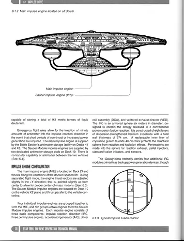
The main impulse engine (MIE) is located on Deck 23 and thrusts along the centerline of the docked spacecraft. During separated flight mode, the engine thrust vectors are adjusted slightly in the +Y direction; that is, pointed slightly up from center to allow for proper center-of-mass motions (See: 6.3). The Saucer Module impulse engines are located on Deck 10 on the vehicle XZ plane and thrust parallel to the vehicle centerline.
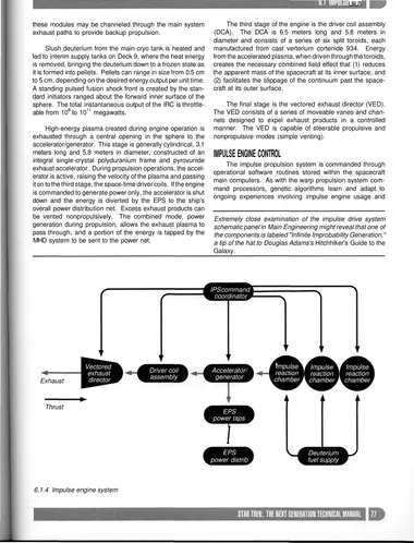
Four individual impulse engines are grouped together to form the MIE, and two groups of two engines form the Saucer Module impulse engines. Each impulse engine consists of three basic components: impulse reaction chamber (IRC, three per impulse engine), accelerator/generator (A/G), driver coil assembly (DCA), and vectored exhaust director (VED). The IRC is an armored sphere six meters in diameter, designed to contain the energy released in a conventional proton-proton fusion reaction. It is constructed of eight layers of dispersion-strengthened hafnium excelinide with a total wall thickness of 674 cm. A replaceable inner liner of crystalline gulium fluoride 40 cm thick protects the structural sphere from reaction and radiation effects. Penetrations are made into the sphere for reaction exhaust, pellet injectors, standard fusion initiators, and sensors.
The Galaxy class normally carries four additional IRC modules primarily as backup power generation devices, though these modules may be channeled through the main system exhaust paths to provide backup propulsion.
Slush deuterium from the main cryo tank is heated and fed to interim supply tanks on Deck 9, where the heat energy is removed, bringing the deuterium down to a frozen state as it is formed into pellets. Pellets can range in size from 0.5 cm to 5 cm, depending on the desired energy output per unit time. A standing pulsed fusion shock front is created by the standard initiators ranged about the forward inner surface of the sphere. The total instantaneous output of the IRC is throttleable from 108 to 1011 megawatts.
High-energy plasma created during engine operation is exhausted through a central opening in the sphere to the accelerator/generator. This stage is generally cylindrical, 3.1 meters long and 5.8 meters in diameter, constructed of an integral single-crystal polyduranium frame and pyrovunide exhaust accelerator. During propulsion operations, the accelerator is active, raising the velocity of the plasma and passing it on to the third stage, the space-time driver coils. If the engine is commanded to generate power only, the accelerator is shut down and the energy is diverted by the EPS to the ship's overall power distribution net. Excess exhaust products can be vented nonpropulsively. The combined mode, power generation during propulsion, allows the exhaust plasma to pass through, and a portion of the energy is tapped by the MHD system to be sent to the power net.
The third stage of the engine is the driver coil assembly (DCA). The DCA is 6.5 meters long and 5.8 meters in diameter and consists of a series of six split toroids, each manufactured from cast verterium cortenide 934. Energy from the accelerated plasma, when driven through the toroids, creates the necessary combined field effect that (1) reduces the apparent mass of the spacecraft at its inner surface, and (2) facilitates the slippage of the continuum past the spacecraft at its outer surface.
The final stage is the vectored exhaust director (VED). The VED consists of a series of moveable vanes and channels designed to expel exhaust products in a controlled manner. The VED is capable of steerable propulsive and nonpropulsive modes (simple venting).
Impulse Engine Control
The impulse propulsion system is commanded through operational software routines stored within the spacecraft main computers. As with the warp propulsion system command processors, genetic algorithms learn and adapt to ongoing experiences involving impulse engine usage and make appropriate modifications in handling both voluntary external commands and purely autonomic operations. Voice commands and keyboard inputs are confirmed and reconciled by the current active main computer, and then handed off to the IPS command coordinator for routing to the engines for execution. The IPS command coordinator is cross-linked with its counterpart in the WPS for flight transitions involving warp entry and exit. Specific software routines react to prevent field energy fratricide (unwanted conflicts between warp fields and impulse engine fields). The command coordinator is also crosslinked with the reaction control system (RCS) for attitude and translational control at all speeds.