2.3 Hull Layers
Details the multiple exterior shell layers of the spacecraft, including substrate, thermal insulation, radiation attenuation, and ablative outer hull.
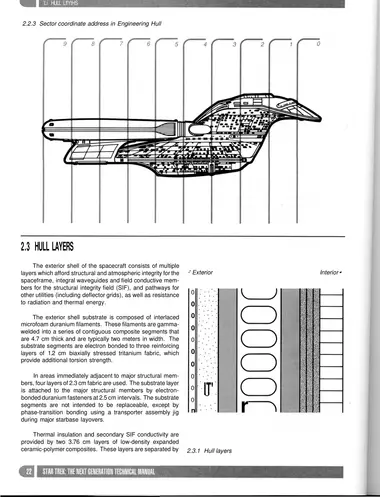
The exterior shell of the spacecraft consists of multiple layers which afford structural and atmospheric integrity for the spaceframe, integral waveguides and field conductive members for the structural integrity field (SIF), and pathways for other utilities (including deflector grids), as well as resistance to radiation and thermal energy.
The exterior shell substrate is composed of interlaced microfoam duranium filaments. These filaments are gammawelded into a series of contiguous composite segments that are 4.7 cm thick and are typically two meters in width. The substrate segments are electron bonded to three reinforcing layers of 1.2 cm biaxially stressed tritanium fabric, which provide additional torsion strength.
In areas immediately adjacent to major structural members, four layers of 2.3 cm fabric are used. The substrate layer is attached to the major structural members by electronbonded duranium fasteners at 2.5 cm intervals. The substrate segments are not intended to be replaceable, except by phase-transition bonding using a transporter assembly jig during major starbase layovers.
Thermal insulation and secondary SIF conductivity are provided by two 3.76 cm layers of low-density expanded ceramic-polymer composites. These layers are separated by an 8.7 cm multiaxis tritanium truss framework, which provides additional thermal insulation and a pass-through for fixed utility conduits.
Radiation attenuation is provided by a 4.2 cm layer of monocrystal beryllium silicate infused with semiferrous polycarbonate whiskers. This layer is networked with a series of 2.3 cm x 0.85 cm molybdenum-jacketed conduits. These conduits, which occur at 130 cm intervals, serve as triphase waveguides for the secondary structural integrity field. Conductive tritanium rods penetrate the waveguides at 10 cm intervals and transfer SIF energy into the ceramic-polymer conductive layer.
The outermost hull layer is composed of a 1.6 cm sheet of AGP ablative ceramic fabric chemically bonded onto a substrate of 0.15 cm tritanium foil. This material is formed into segments of approximately 3.7 m2 and is attached to the radiation attenuation layer by a series of duranium fasteners, which allows individual segments to be replaced as necessary. (Micrometeoroid erosion is kept to a minimum by the deflector shield system, but is sufficient to warrant replacement of 30% of leading-edge segments on the average of every 7.2 Standard years.) Individual outer hull segments are machined to a tolerance of +0.5 mm to allow for minimum drag through the interstellar medium. Joints between segments are manufactured to a tolerance of ±0.25 mm.
Also incorporated into the outermost hull layer is a series of superconducting molybdenum-jacketed waveguide conduits which serves to distribute and disperse the energy of the tactical deflector system. Selected segments of this network also serve as radiators for starship thermal management.