11.7 Personal Phasers
Covers the Type I, II, and III personal phasers, their internal hardware and operation, the sixteen power settings and their effects, overload safety considerations, and personnel training.
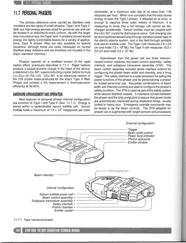
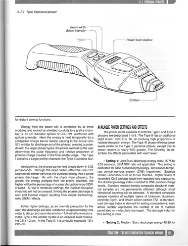
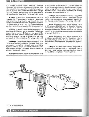
The primary defensive arms carried by Starfleet crew members are two types of small phasers, Type I and Type II. Both are high-energy devices sized for personal use and can be stowed in or attached to one's uniform. As with the larger ship-mounted arrays, the Type I and II phasers convert stored energy into tightly controllable beams for a variety of applications. Type III phaser rifles are also available for special situations, although these are rarely necessary on normal Starfleet away missions and are therefore not included in the ship's standard inventory.
Phasers operate on a modified version of the rapid nadion effect, previously described in 11.1. Rapid nadions produce a pulsed protonic charge in the heart of the device, a stabilized LiCu 521 superconducting crystal (lattice formula Li<>Cu>
Hardware Arrangement And Operation
Most features of personal phaser internal configuration are common to Type I and Type II (See: 11.7.1). Energy is stored within a replenishable sarium krellide cell. Sarium krellide holds a maximum of 1.3 x 10⁶ megajoules per cubic centimeter, at a maximum leak rate of no more than 1.05 kilojoules per hour. When one considers that the total stored energy of even the Type I phaser, if released all at once, is enough to vaporize three cubic meters of tritanium, it is reassuring to know that a full storage cell cannot be discharged accidentally. Sarium krellide must be coupled with the LiCu 521 crystal for discharge to occur. Cell charging can be accomplished aboard ship through standard power taps of the electro plasma system, and in the field through portable bulk sarium krellide units. The Type I cell measures 2.4 x 3.0 cm and holds 7.2 x 10⁶ MJ; the Type II cell measures 10.2 x 3.0 cm and holds 4.5 x 10⁷ MJ.
Downstream from the power cell are three interconnected control modules: the beam control assembly, safety interlock, and subspace transceiver assembly (STA). The beam control assembly includes tactile interface buttons for configuring the phaser beam width and intensity, and a firing trigger. The safety interlock is a code processor for safing the power functions of the phaser and for personalizing a phaser for limited personnel use. Key-press combinations of beam width and intensity controls are used to configure the phaser's safety condition. The STA is used as part of the safety system while aboard Starfleet vessels. It maintains contact between the phaser and the ship computers to assure that power levels are automatically restrained during shipboard firings, usually limited to heavy stun. Emergency override commands may be keyed in by the beam controls. The STA adapted for phaser use is augmented with target sensors and processors for distant aiming functions.
Energy from the power cell is controlled by all three modules and routed by shielded conduits to a prefire chamber, a 1.5 cm diameter sphere of LiCu 521 reinforced with gulium arkenide. Here the energy is held temporarily by a collapsible charge barrier before passing to the actual LiCu 521 emitter for discharge out of the phaser, creating a pulse. As with the larger phaser types, the power level set by the user determines the pulse frequency and relative proportion of protonic charge created in the final emitter stage. The Type I contains a single prefire chamber; the Type II contains four.
At triggering, the charge barrier field breaks down in 0.02 picoseconds. Through the rapid nadion effect the LiCu 521 segmented emitter converts the pumped energy into a tuned phaser discharge. As with the ship's main phasers, the greater the energy pumped from the prefire chamber, the higher will be the percentage of nuclear disruption force (NDF) created. At low to moderate settings, the nuclear disruption threshold will not be crossed, limiting the phaser discharge to stun and thermal impact resulting from simple electromagnetic (SEM) effects.
At the higher settings, as an override precaution for the user, the discharge will take a distance of approximately one meter to decay and recombine to form full-lethality emissions. In the Type I, the emitter crystal is an elliptical solid measuring 0.5 x 1.2 cm. In the Type II, it is a regular trapezoid 1.5 x 2.85 cm.
Available Power Settings And Effects
The power levels available to both the Type I and Type II phasers are designated 1 to 8. The Type II has an additional eight levels, from 9 to 16, all involving high proportions of nuclear disruption energy. The Type III phaser rifle has power levels similar to the Type II personal phaser, except that its power reserve is nearly 50% greater. The following list describes the effects associated with each level:
- Setting 1: Light Stun; discharge energy index 15.75 for 0.25 seconds, SEM:NDF ratio not applicable. This setting is calibrated for base humanoid physiology, and causes temporary central nervous system (CNS) impairment. Subjects remain unconscious for up to five minutes. Higher levels of reversible CNS damage result from repeated long exposures. The discharge energy index is related to RNE protonic charge levels. Standard median-density composite structural material samples are not permanently affected, although small vibrational warming will be detected. A standard composite sample consists of multiple layers of tritanium, duranium, cortenite, lignin, and lithium-silicon-carbon 372. A standardized damage index is derived for setting comparisons; each whole number represents the number of cm of material penetrated or molecularly damaged. The damage index for this setting is zero.
- Setting 2: Medium Stun; discharge energy 45.30 for 0.75 seconds, SEM:NDF ratio not applicable. Base-type humanoids are rendered unconscious for up to fifteen minutes, resistant humanoids up to five minutes. Long exposures produce low levels of irreversible CNS and epithelial damage. Structural materials are not affected, though higher levels of vibrational warming are evident. The damage index is zero.
- Setting 3: Heavy Stun; discharge energy 160.65 for 1.025 seconds, SEM:NDF ratio not applicable. Base humanoids remain in a sleep state for approximately one hour, resistant bioforms for fifteen minutes. Single discharges raise 1cc of liquid water by 100°C. Structural samples experience significant levels of thermal radiation. The damage index is 1.
- Setting 4: Thermal Effects; discharge energy 515.75 for 1.5 seconds, SEM:NDF ratio not applicable. Base humanoids experience extensive CNS damage and epidermal EM trauma. Structural materials exhibit visible thermal shock. Discharges of longer than five seconds produce deep heat storage effects within metal alloys. The damage index is 3.5.
- Setting 5: Thermal Effects; discharge energy 857.5 for 1.5 seconds, SEM:NDF ratio 250:1. Humanoid tissue experiences severe burn effects but, due to water content, deep layers will not char. Simple personnel forcefields are penetrated after five seconds. Large Away Team fields will not be affected. The damage index is 7.
- Setting 6: Disruption Effects; discharge energy 2,700 for 1.75 seconds, SEM:NDF ratio 90:1. Organic tissues and structural materials exhibit comparable penetration and molecular damage effects as higher energies cause matter to dissociate rapidly. Familiar thermal effects begin decreasing at this level. The damage index is 15.
- Setting 7: Disruption Effects; discharge energy 4,900 for 1.75 seconds, SEM:NDF ratio 1:1. Organic tissue damage causes immediate cessation of life processes, since disruption effects become widespread. The damage index is 50.
- Setting 8: Disruption Effects; discharge energy 15,000 for 1.75 seconds, SEM:NDF ratio 1:3. Cascading disruption forces cause humanoid organisms to vaporize, as 50% of affected matter transitions out of the continuum. The damage index is 120; all unprotected matter is affected and penetrated according to depth/time.
- Setting 9: Disruption Effects; discharge energy 65,000 for 1.5 seconds, SEM:NDF ratio 1:7. The damage index is 300; medium alloy or ceramic structural materials over 100 cm thickness begin exhibiting energy rebound prior to vaporization.
- Setting 10: Disruption Effects; discharge energy 125,000 for 1.3 seconds, SEM:NDF ratio 1:9. The damage index is 450; heavy alloy structural materials absorb or rebound energy, 0.55 sec delay before material vaporizes.
- Setting 11: Explosive/Disruption Effects; discharge energy 300,000 for 0.78 seconds, SEM:NDF ratio 1:11. The damage index is 670; ultradense alloy structural materials absorb/rebound energy, 0.20 sec delayed reaction before material vaporizes. Light geologic displacement; <10 m3 rock/ore of 6.0 g/cm3 explosively uncoupled per discharge.
- Setting 12: Explosive/Disruption Effects; discharge energy 540,000 for 0.82 seconds, SEM:NDF ratio 1:14. The damage index is 940; ultradense alloy structural materials absorb/rebound energy, 0.1 sec delayed reaction before material vaporizes. Medium geologic displacement; <50 m3 rock/ore of 6.0 g/cm3 explosively uncoupled per discharge.
- Setting 13: Explosive/Disruption Effects; discharge energy 720,000 for 0.82 seconds, SEM:NDF ratio 1:18. The damage index is 1,100; shielded matter exhibits minor vibrational heating effects. Medium geologic displacement; <90 m3 rock/ore of 6.0 g/cm3 explosively uncoupled per discharge.
- Setting 14: Explosive/Disruption Effects; discharge energy 930,000 for 0.75 seconds, SEM:NDF ratio 1:20. The damage index is 1,430; shielded matter exhibits medium vibrational heating effects. Heavy geologic displacement; <160 m3 rock/ore of 6.0 g/cm3 explosively uncoupled per discharge.
- Setting 15: Explosive/Disruption Effects; discharge energy 1.17 x 10⁶ for 0.32 seconds, SEM:NDF ratio 1:25. The damage index is 1,850; shielded matter exhibits major vibrational heating effects. Heavy geologic displacement; <370 m3 rock/ore of 6.0 g/cm3 explosively uncoupled per discharge.
- Setting 16: Explosive/Disruption Effects; discharge energy 1.55 x 10⁶ for 0.28 seconds, SEM:NDF ratio 1:40. The damage index is 2,450; shielded matter exhibits light mechanical fracturing damage. Heavy geologic displacement; <650 m3 rock/ore of 6.0 g/cm3 explosively uncoupled per discharge.
Safety Considerations
As a result of the basic physics required to produce a phaser discharge, an undesirable but unavoidable process exists, namely that of phaser overload. The accepted methods employed for energy storage, flow, control, and discharge allow for an amplified rebounding to occur from the storage cell to the prefire chamber, and simultaneously back to the storage cell. While the total energy within the system remains the same, the flow pressure is elevated during the rebound, to the point where the storage cell cannot reabsorb the energy fast enough. The barrier field will be reinforced during this buildup, effectively preventing normal discharge through the emitter.
Conductive acoustic effects manifest themselves during overload, ranging from 6 kHz to over 20 kHz within thirty seconds. Explosive destruction of the phaser will occur when the energy level exceeds the prefire chamber's density and structural limits.
The safety interlock will prevent overload under most operating conditions, though the design specifications could not cope with some forms of tampering. This can become a priority security matter should a standard-issue phaser fall into the hands of a Threat force.
Personnel Training And Operations
All Starfleet and attached personnel receive initial basic instruction on the operation and use of a low-power variant of the Type I phaser (limited to Setting 3). All Starfleet officers receive advanced training and are issued full-power Type I phasers as personal defensive arms. During Alert conditions aboard ship and during Away Missions, the Security Division will oversee the distribution of Type II units. Training for the use of Type III phaser rifles is available on starbases only.
Continued proficiency training in defensive techniques is maintained at four-month intervals for shipboard personnel, and at one-month intervals for Away Team candidates. Each Security Division officer's continuing phaser training progresses at varied rates, depending on individual specialties.