TNG Manual · Visual Records
Technical Schematics
163 figures and diagrams. Select any plate to enlarge.
1 · USS Enterprise Introduction
1.1.1 Galaxy Class Starship Development Project logo
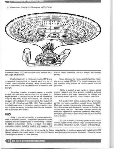
1.1.2 Galaxy class Starship USS Enterprise, NCC-1701-D
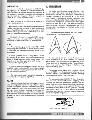
1.2.1 The original Enterprise emblem (ca. 2245) and the current version of the Starfleet emblem
1.2.2 USS Enterprise, NCC-1701
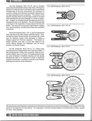
1.2.3 USS Enterprise, NCC-1701-A
1.2.4 USS Enterprise, NCC-1701 -B
1.2.5 USS Enterprise, NCC-1701-C
1.2.6 USS Enterprise, NCC-1701-D
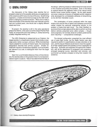
1.3.1 Galaxy class starship Enterprise
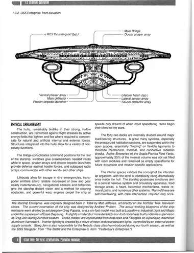
1.3.2 USS Enterprise front elevation
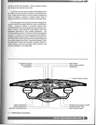
1.3.3 USS Enterprise aft elevation
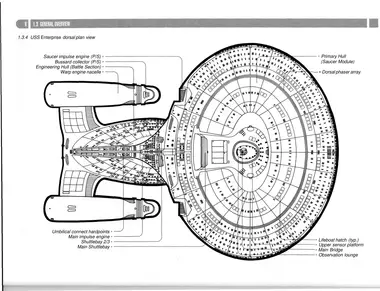
1.3.4 USS Enterprise dorsal plan view
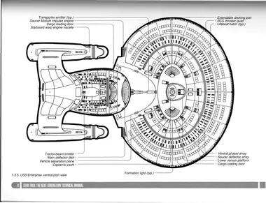
1.3.5 USS Enterprise ventral plan view
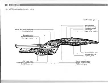
1.3.6 USS Enterprise starboard elevation, exterior
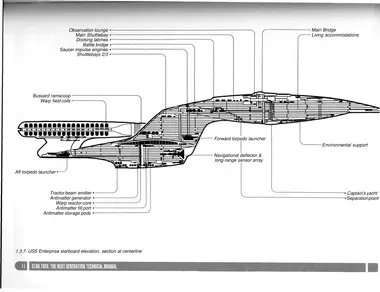
1.3.7 USS Enterprise starboard elevation, section at centerline
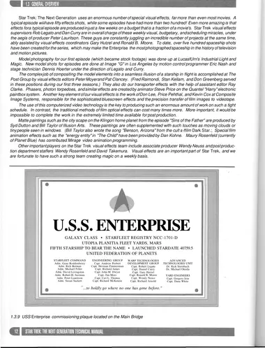
1.3.9 USS Enterprise commissioning plaque located on the Main Bridge
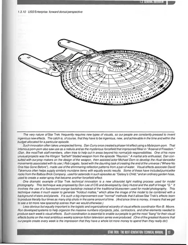
1.3.10 USS Enterprise forward dorsal perspective
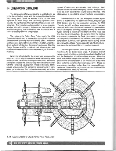
1.4.1 Assembly facility at Utopia Planitia Fleet Yards, Mars
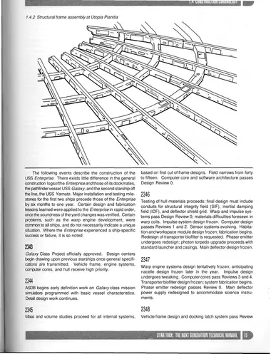
1.4.2 Structural frame assembly at Utopia Planitia
2 · Spacecraft Structure
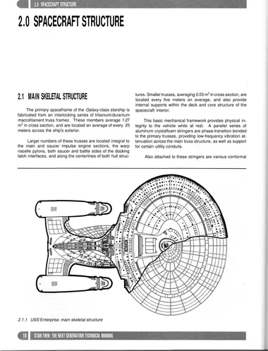
2.1.1 USS Enterprise main skeletal structure
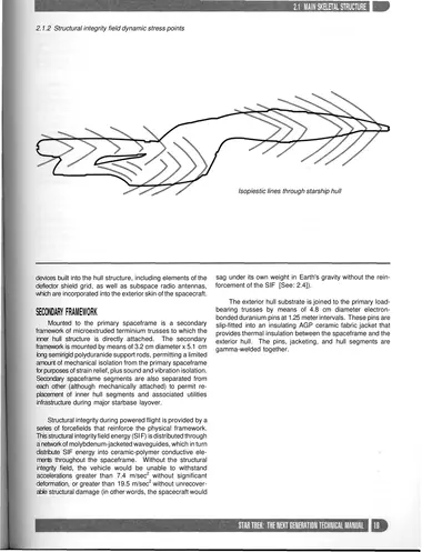
2.1.2 Structural integrity field dynamic stress points
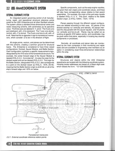
2.2.1 External coordinate reference station points
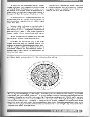
2.2.2 Saucer Module sector coordinate (third digit in internal coordinate address)
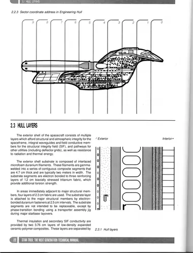
2.2.3 Sector coordinate address in Engineering Hull
2.3.1 Hull layers
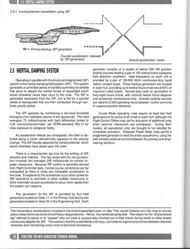
2.5.1 Inertial potential cancellation using IDF
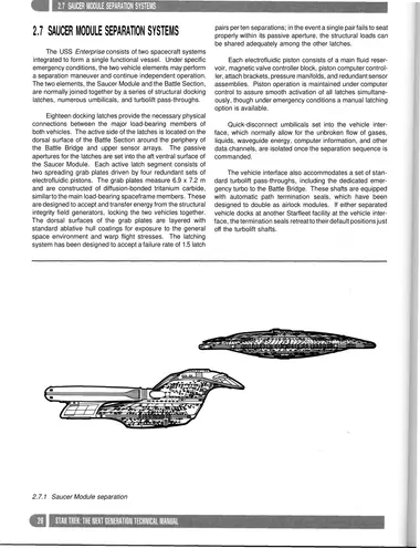
2.7.1 Saucer Module separation
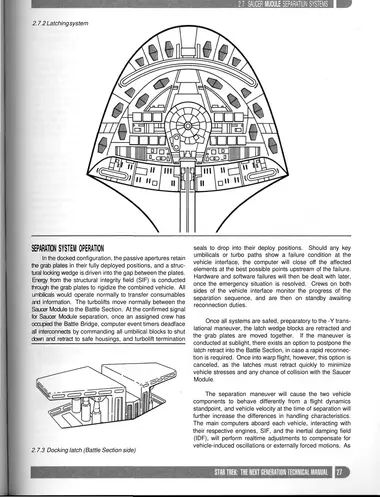
2.7.2 Latching system
2.7.3 Docking latch (Battle Section side)
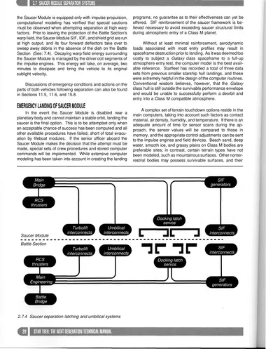
2.7.4 Saucer separation latching and umbilical systems
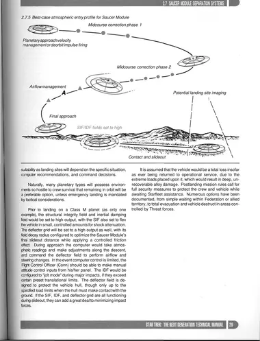
2.7.5 Best-case atmospheric entry profile for Saucer Module
3 · Command Systems
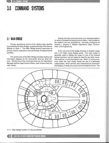
3.1.1 Main Bridge location on Saucer Module
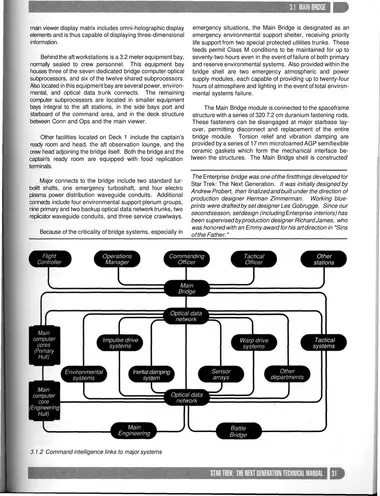
3.1.2 Command intelligence links to major systems
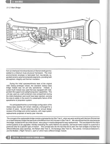
3.1.3 Main Bridge
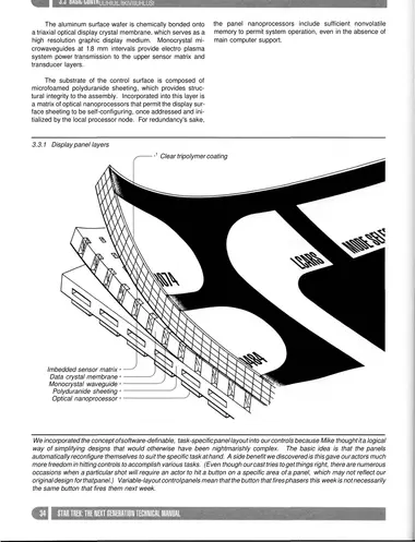
3.3.1 Display panel layers
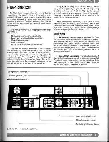
3.4.1 Flight Control panel (Cruise Mode)
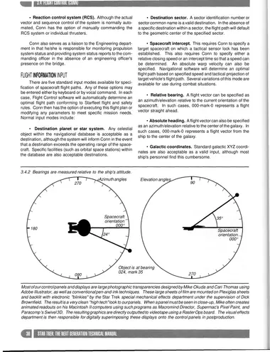
3.4.2 Bearings are measured relative to the ship's attitude.
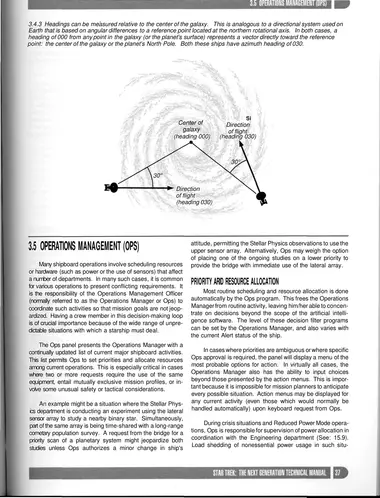
3.4.3 Headings can be measured relative to the center of the galaxy. This is analogous to a directional system used on Earth that is based on angular differences to a reference point located at the northern rotational axis. In both cases, a heading of 000 from any point in the galaxy (or the planet's surface) represents a vector directly toward the reference point: the center of the galaxy or the planet's North Pole. Both these ships have azimuth heading of 030.
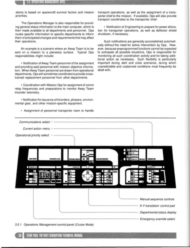
3.5.1 Operations Management control panel (Cruise Mode)
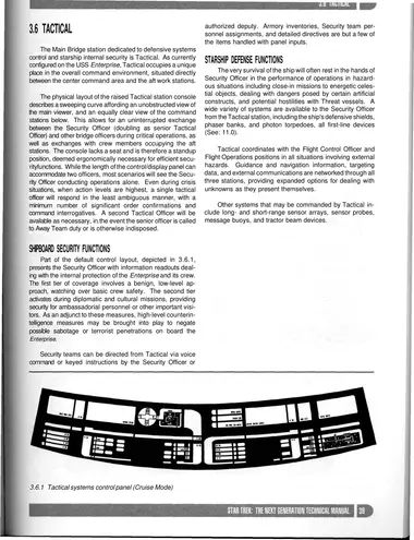
3.6.1 Tactical systems control panel (Cruise Mode)
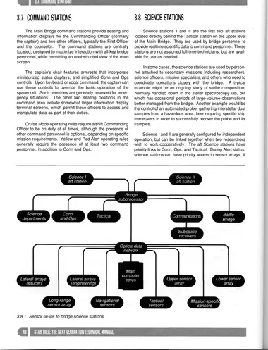
3.8.1 Sensor tie-ins to bridge science stations
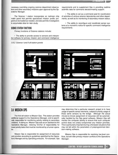
3.8.2 Science I and II aft station panels
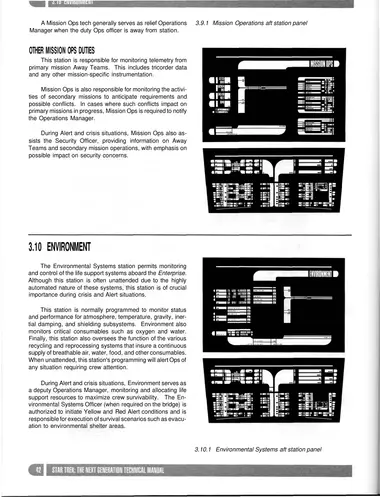
3.9.1 Mission Operations aft station panel
3.10.1 Environmental Systems aft station panel
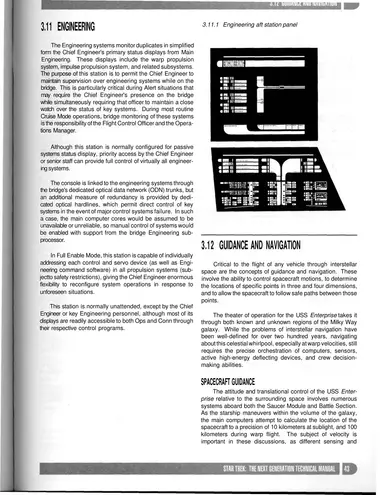
3.11.1 Engineering aft station panel
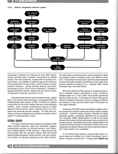
3.12.1 Galactic navigational reference system
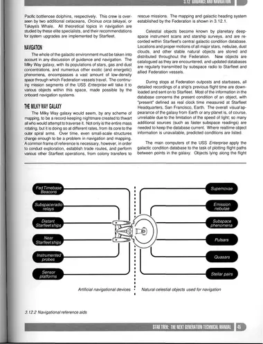
3.12.2 Navigational reference aids
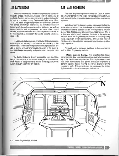
3.15.1 Main Engineering, aft view
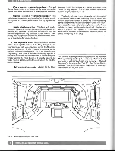
3.15.2 Main Engineering forward view
4 · Computer Systems
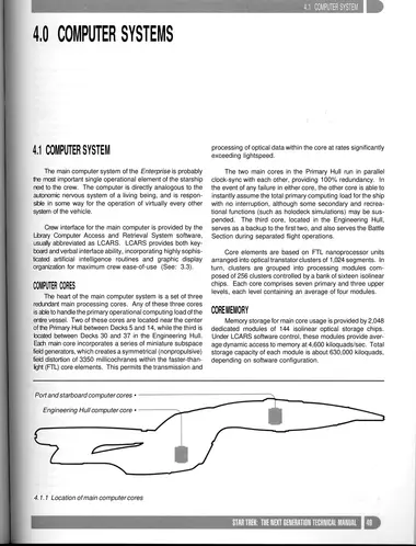
4.1.1 Location of main computer cores
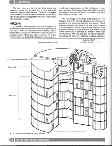
4.1.2 Cross section of typical computer core
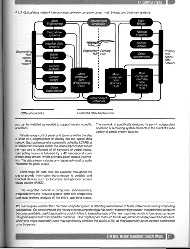
4.1.3 Optical data network interconnects between computer cores, main bridge, and other key systems
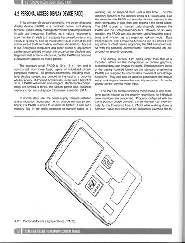
4.2.1 Personal Access Display Device (PADD)
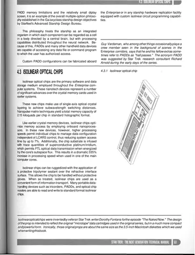
4.3.1 Isolinear optical chip
5 · Warp Propulsion Systems
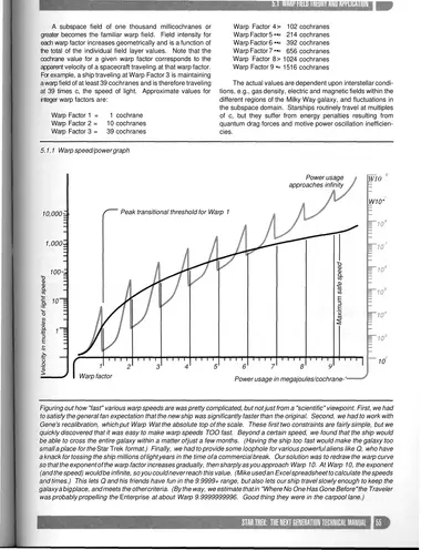
5.1.1 Warp speed/power graph
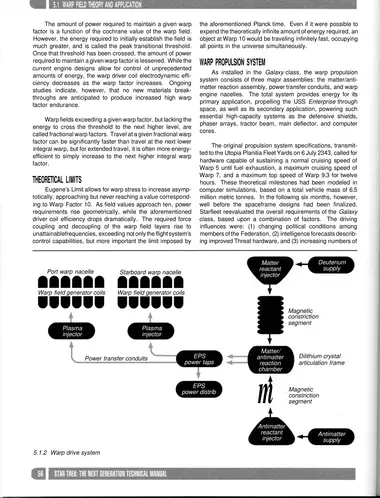
5.1.2 Warp drive system
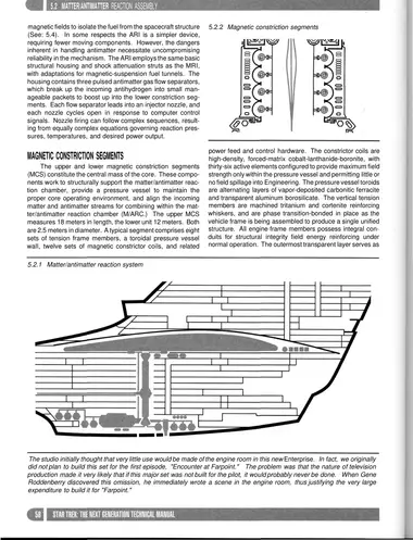
5.2.1 Matter/antimatter reaction system
5.2.2 Magnetic constriction segments
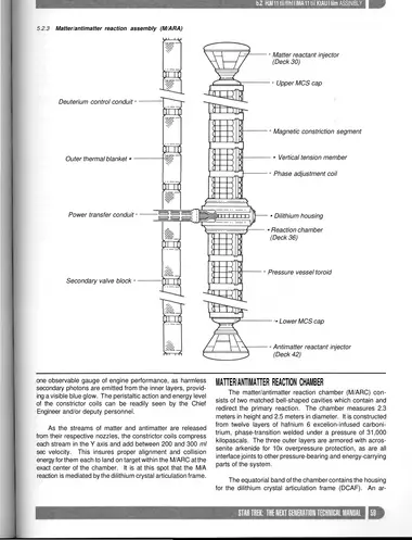
5.2.3 Matter/antimatter reaction assembly (M/ARA)
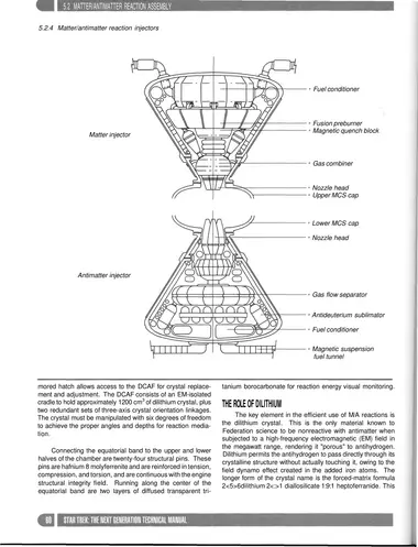
5.2.4 Matter/antimatter reaction injectors
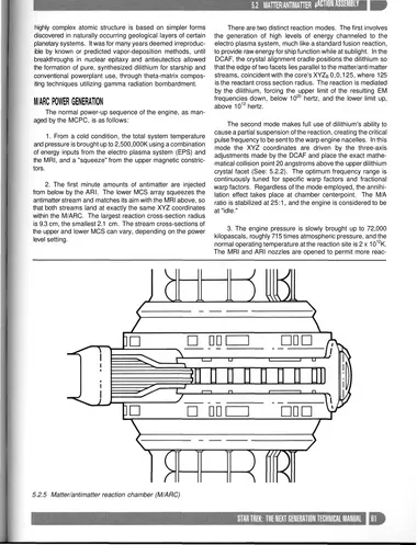
5.2.5 Matter/antimatter reaction chamber (M/ARC)
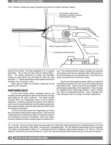
5.2.6 Dilithium crystals are used to regulate and control the matter-antimatter reaction.
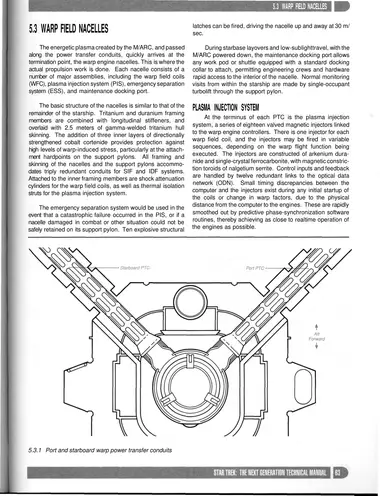
5.3.1 Port and starboard warp power transfer conduits
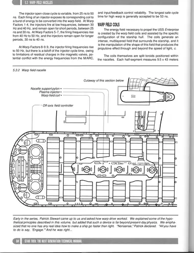
5.3.2 Warp field nacelle
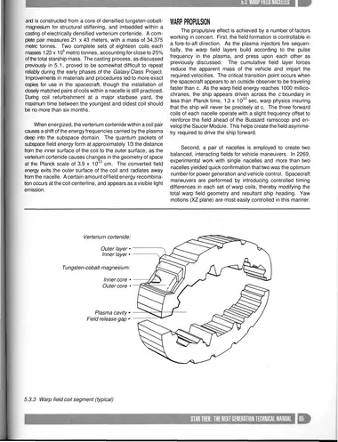
5.3.3 Warp field coil segment (typical)
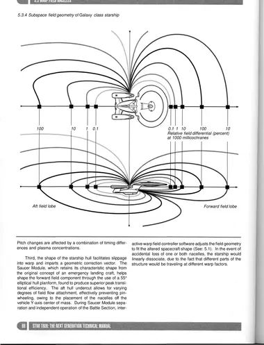
5.3.4 Subspace field geometry of Galaxy class starship
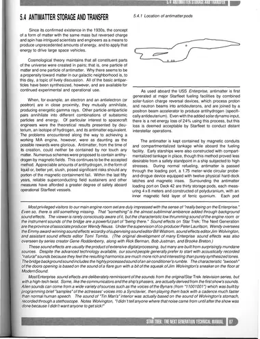
5.4.1 Location of antimatter pods
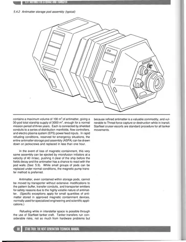
5.4.2 Antimatter storage pod assembly (typical)
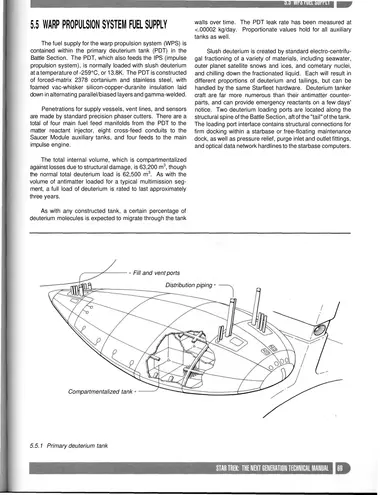
5.5.1 Primary deuterium tank
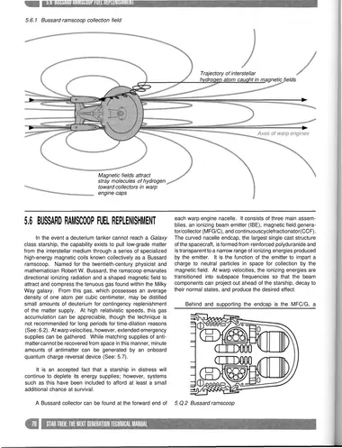
5.6.1 Bussard ramscoop collection field
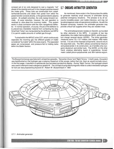
5.7.1 Antimatter generator
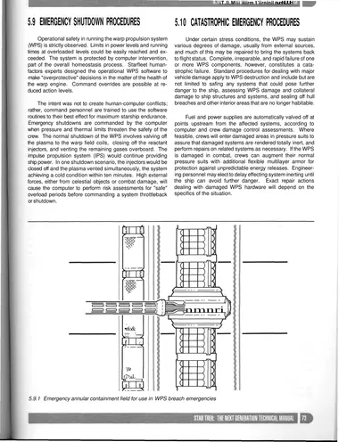
5.9.1 Emergency annular containment field for use in WPS breach emergencies
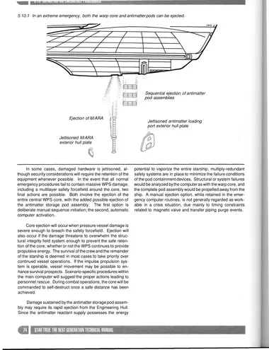
5.10.1 In an extreme emergency, both the warp core and antimatter pods can be ejected.
6 · Impulse Propulsion Systems
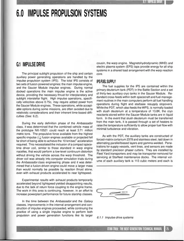
6.1.1 Impulse drive systems
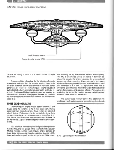
6.1.2 Main impulse engine located on aft dorsal
6.1.3 Typical impulse fusion reactor
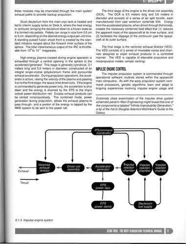
6.1.4 Impulse engine system
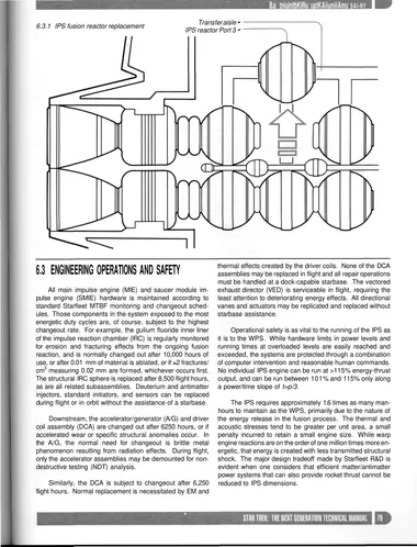
6.3.1 IPS fusion reactor replacement Transfer aisle • IPS reactor Port 3 •
7 · Utilities and Auxiliary Systems
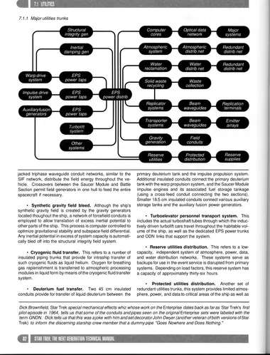
7.1.1 Major utilities trunks
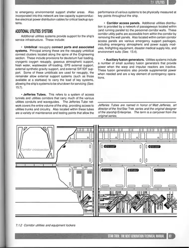
7.1.2 Corridor utilities and equipment lockers
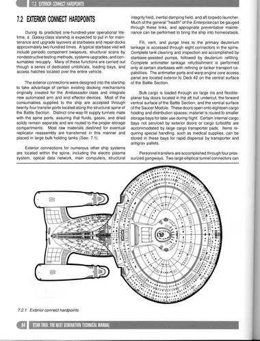
7.2.1 Exterior connect hardpoints
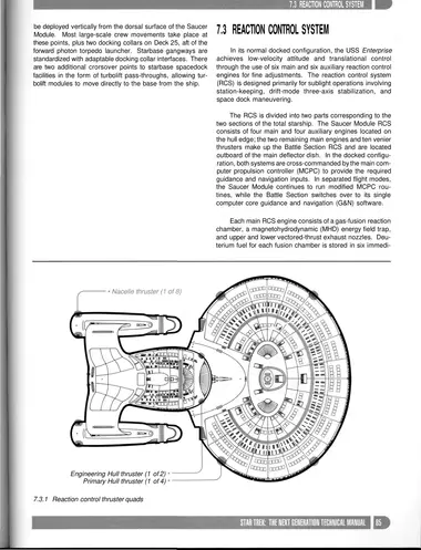
7.3.1 Reaction control thruster quads
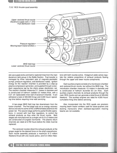
7.3.2 RCS thruster quad assembly
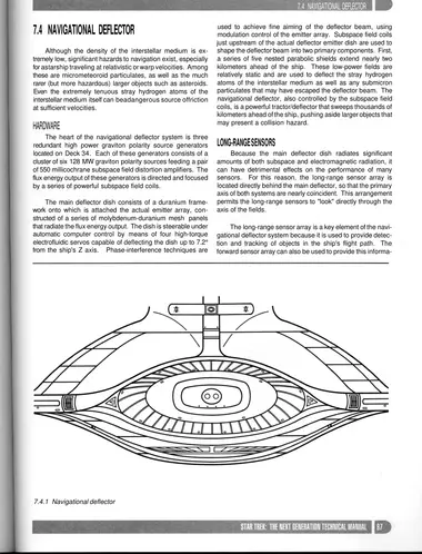
7.4.1 Navigational deflector
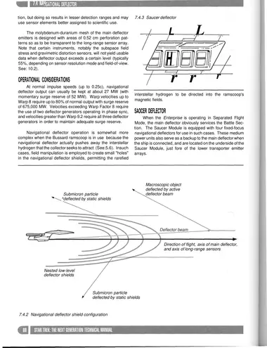
7.4.2 Navigational deflector shield configuration
7.4.3 Saucer deflector
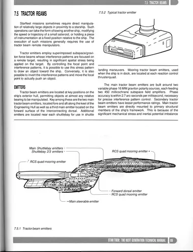
7.5.1 Tractor beam emitters
7.5.2 Typical tractor emitter
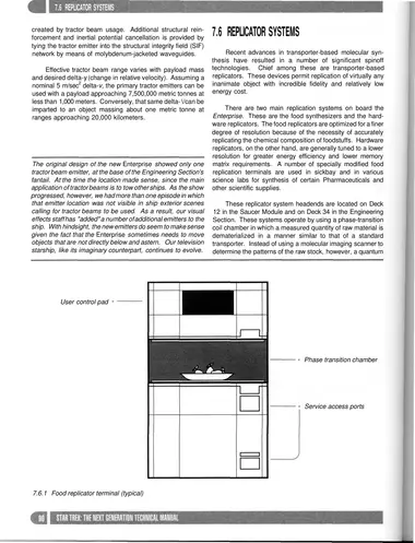
7.6.1 Food replicator terminal (typical)
8 · Communications
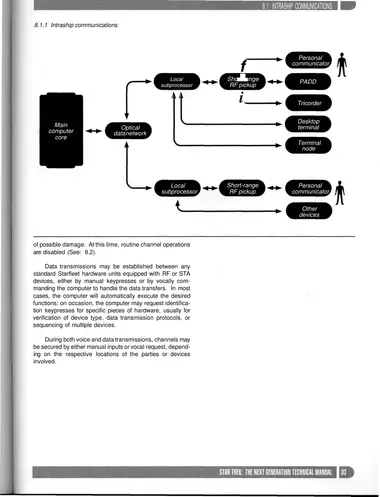
8.1.1 Intraship communications
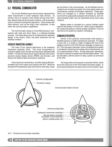
8.2.1 Personal communicator assembly
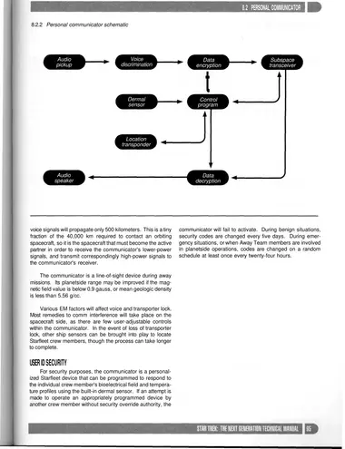
8.2.2 Personal communicator schematic
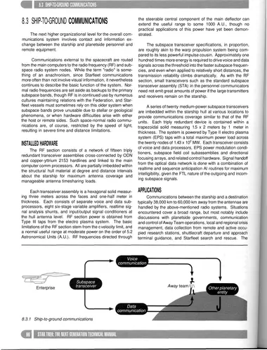
8.3.1 Ship-to-ground communications
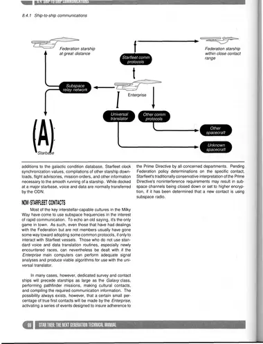
8.4.1 Ship-to-ship communications
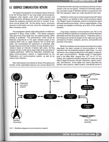
8.5.1 Starfleet subspace communications network
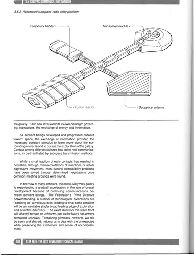
8.5.2 Automated subspace radio relay platform
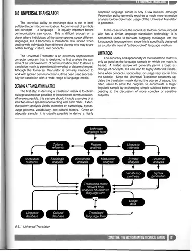
8.6.1 Universal Translator
9 · Transporter Systems
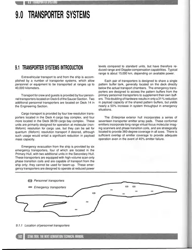
9.1.1 Location of personnel transporters
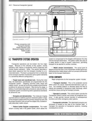
9.2.1 Personnel transporter (typical)
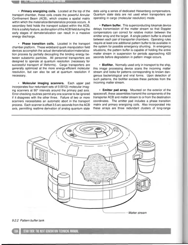
9.2.2 Pattern buffer tank
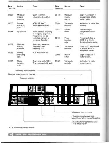
9.2.3 Transporter control console
10 · Science and Remote Sensing Systems
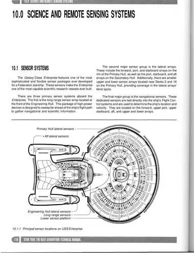
10.1.1 Principal sensor locations on USS Enterprise
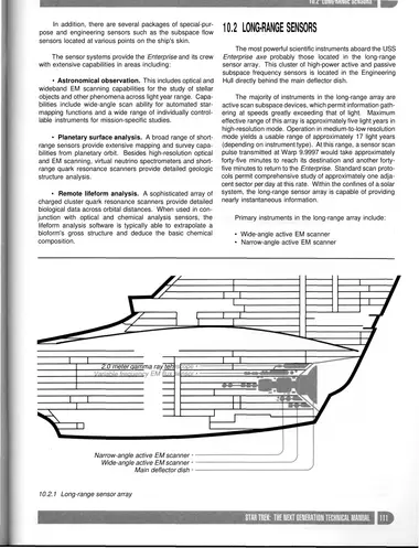
10.2.1 Long-range sensor array
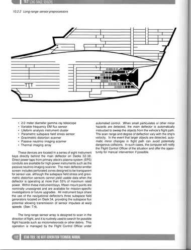
10.2.2 Long-range sensor preprocessors
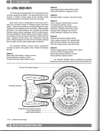
10.4.1 Lateral sensor arrays
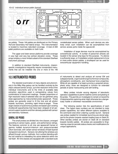
10.4.2 Individual sensor pallet (typical)
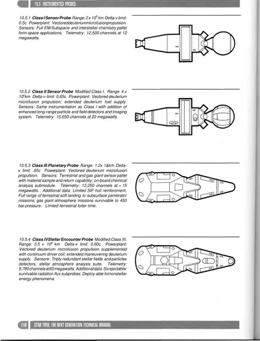
10.5.1 Class I Sensor Probe Range: 2 x 10⁵ km Delta-v limit: 0.5c Powerplant: Vectored deuterium microfusion propulsion. Sensors: Full EM/Subspace and interstellar chemistry pallet for in-space applications. Telemetry: 12,500 channels at 12 megawatts.
10.5.2 Class II Sensor Probe Modified Class I. Range: 4 x 10s km Delta-v limit: 0.65c Powerplant: Vectored deuterium microfusion propulsion; extended deuterium fuel supply. Sensors: Same instrumentation as Class I with addition of enhanced long-range particle and field detectors and imaging system. Telemetry: 15,650 channels at 20 megawatts.
10.5.3 Class III Planetary Probe Range: 1.2 x 1&km Deltav limit: .65c Powerplant: Vectored deuterium microfusion propulsion. Sensors: Terrestrial and gas giant sensor pallet with material sample and return capability; on-board chemical analysis submodule. Telemetry: 13,250 channels at = 15 megawatts. Additional data: Limited SIF hull reinforcment. Full range of terrestrial soft landing to subsurface penetrator missions; gas giant atmosphere missions survivable to 450 bar pressure. Limited terrestrial loiter time.
10.5.4 Class IV Stellar Encounter Probe Modified Class III. Range: 3.5 x 10⁶ km Delta-v limit: 0.60c Powerplant: Vectored deuterium microfusion propulsion supplemented with continuum driver coil; extended maneuvering deuterium supply. Sensors: Triply redundant stellar fields and particles detectors, stellar atmosphere analysis suite. Telemetry: 9,780 channels at 65 megawatts. Additional data: Six ejectable/survivable radiation flux subprobes. Deployable for nonstellar energy phenomena.
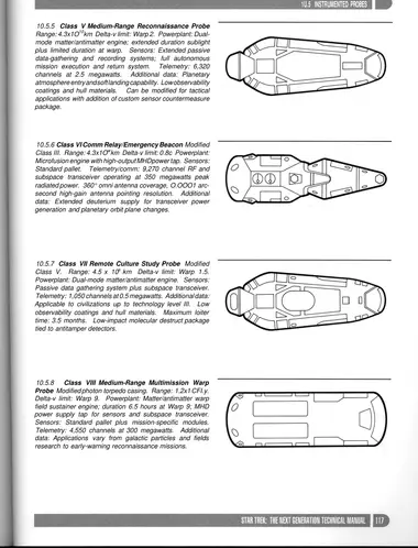
10.5.5 Class V Medium-Range Reconnaissance Probe Range: 4.3 x 10 10 km Delta-v limit: Warp 2. Powerplant: Dualmode matter/antimatter engine; extended duration sublight plus limited duration at warp. Sensors: Extended passive data-gathering and recording systems; full autonomous mission execution and return system. Telemetry: 6,320 channels at 2.5 megawatts. Additional data: Planetary atmosphere entry and soft landing capability. Low observability coatings and hull materials. Can be modified for tactical applications with addition of custom sensor countermeasure package.
10.5.6 Class VI Comm Relay/Emergency Beacon Modified Class III. Range: 4.3 x 10w km Delta-v limit: 0.8c Powerplant: Microfusion engine with high-output MHD power tap. Sensors: Standard pallet. Telemetry/comm: 9,270 channel RF and subspace transceiver operating at 350 megawatts peak radiated power. 360° omni antenna coverage, O.OOO1 arcsecond high-gain antenna pointing resolution. Additional data: Extended deuterium supply for transceiver power generation and planetary orbit plane changes.
10.5.7 Class VII Remote Culture Study Probe Modified Class V. Range: 4.5 x 10s km Delta-v limit: Warp 1.5. Powerplant: Dual-mode matter/antimatter engine. Sensors: Passive data gathering system plus subspace transceiver. Telemetry: 1,050 channels at 0.5 megawatts. Additional data: Applicable to civilizations up to technology level III. Low observability coatings and hull materials. Maximum loiter time: 3.5 months. Low-impact molecular destruct package tied to antitamper detectors.
10.5.8 Class VIII Medium-Range Multimission Warp Probe Modified photon torpedo casing. Range: 1.2 x 10 l.y. Delta-v limit: Warp 9. Powerplant: Matter/antimatter warp field sustainer engine; duration 6.5 hours at Warp 9; MHD power supply tap for sensors and subspace transceiver. Sensors: Standard pallet plus mission-specific modules. Telemetry: 6,500 channels at 230 megawatts. Additional data: Limited payload capacity; isolinear memory storage 3,400 kiloquads; fifty-channel transponder echo. Typical application is emergency log/message capsule on homing trajectory to nearest starbase or known Starfleet vessel position.
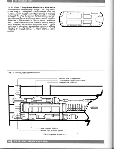
10.5.9 Class IX Long-Range Multimission Warp Probe Modified photon torpedo casing. Range: 7.6 x 10s l.y. Deltav limit: Warp 9. Powerplant: Matter/antimatter warp field sustainer engine; duration twelve hours at Warp 9; extended fuel supply for Warp 8 maximum flight duration of fourteen days. Sensors: Standard pallet plus mission-specific modules.
10.5.10 Forward probe/torpedo launcher
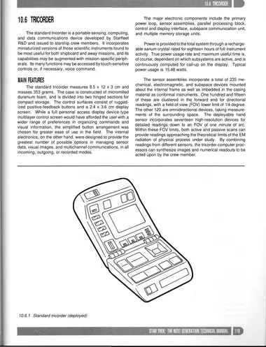
10.6.1 Standard tricorder (deployed)
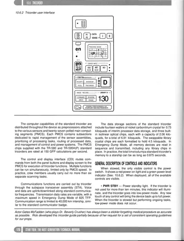
10.6.2 Tricorder user interface
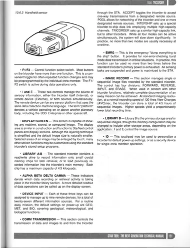
10.6.3 Handheld sensor
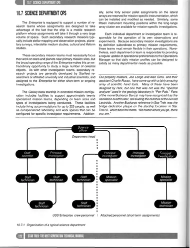
10.7.1 Organization of a typical science department
11 · Tactical Systems
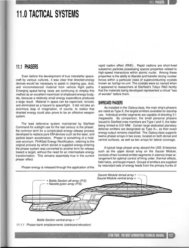
11.1.1 Phaser bank emplacements (starboard elevation)
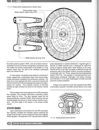
11.1.2 Phaser bank emplacements (dorsal view)
11.1.3 Typical phaser bank element
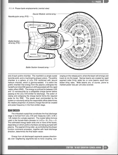
11.1.4 Phaser bank emplacements (ventral view)
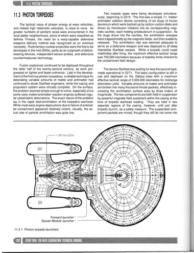
11.3.1 Photon torpedo launchers
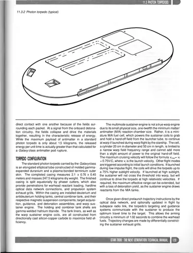
11.3.2 Photon torpedo (typical)
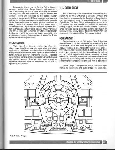
11.5.1 Battle Bridge
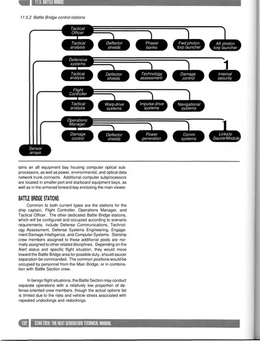
11.5.2 Battle Bridge control stations
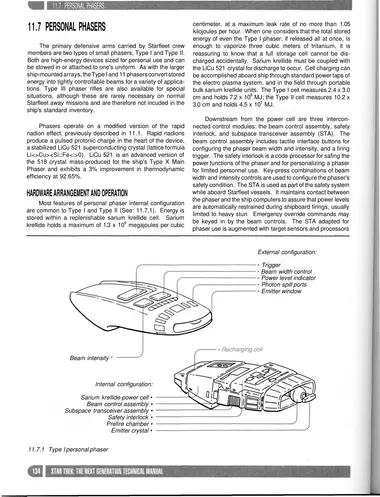
11.7.1 Type I personal phaser
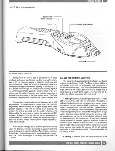
11.7.2 Type II personal phaser
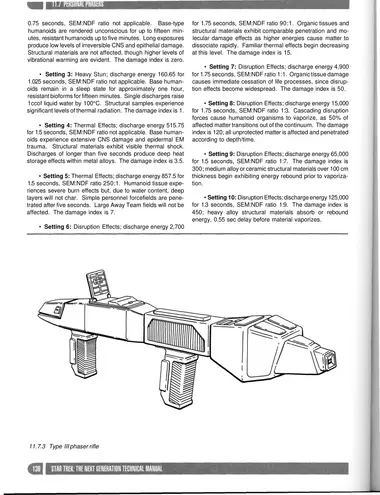
11.7.3 Type III phaser rifle
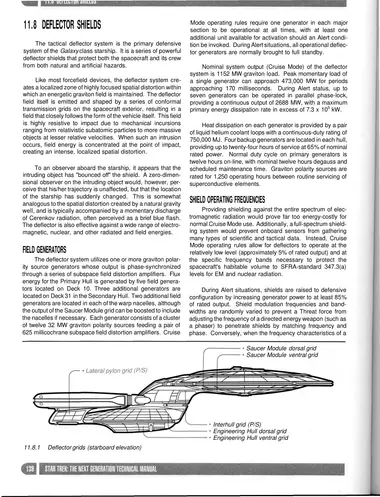
11.8.1 Deflector grids (starboard elevation)
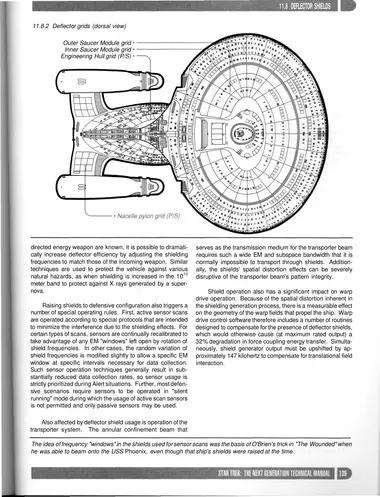
11.8.2 Deflector grids (dorsal view)
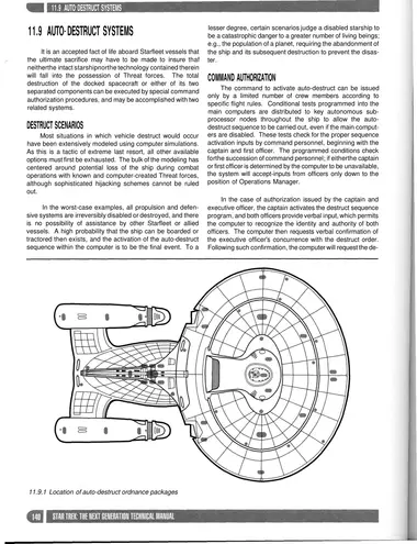
11.9.1 Location of auto-destruct ordnance packages
12 · Environmental Systems
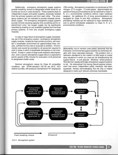
12.2.1 Atmospheric system
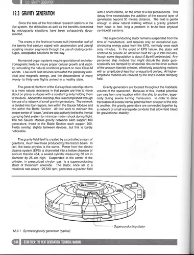
12.3.1 Synthetic gravity generator (typical)
13 · Crew Support Systems
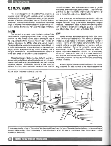
13.2.1 Deck 12 sickbay intensive-care ward
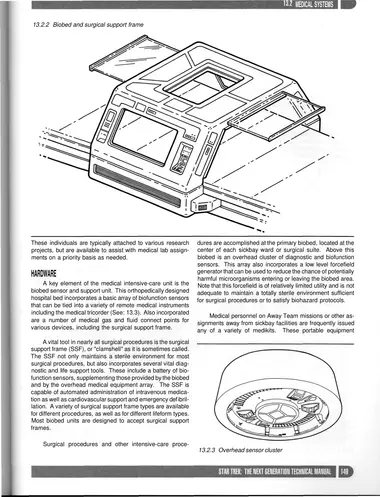
13.2.2 Biobed and surgical support frame
13.2.3 Overhead sensor cluster
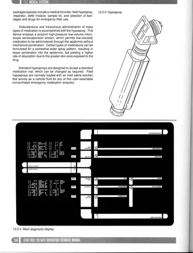
13.2.4 Main diagnostic display
13.2.5 Hypospray
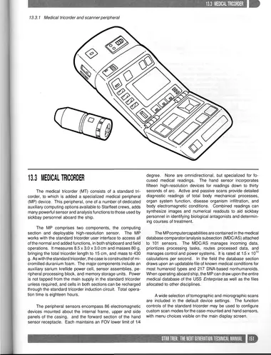
13.3.1 Medical tricorder and scanner peripheral
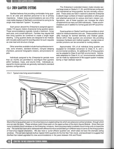
13.4.1 Typical crew living accommodations
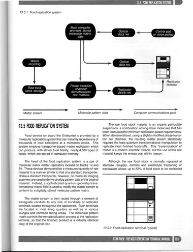
13.5.1 Food replication system
13.5.2 Food replication terminal (typical)
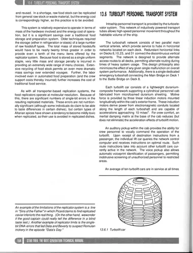
13.6.1 Turbolift car
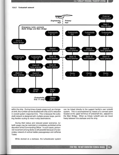
13.6.2 Turboshaft network
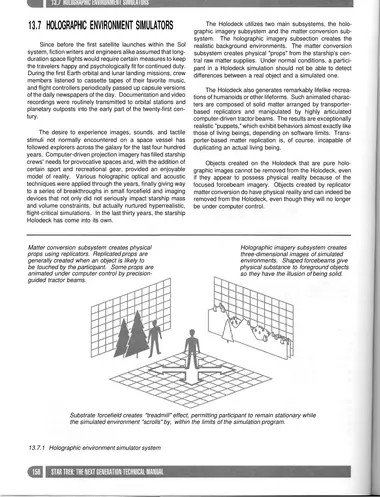
13.7.1 Holographic environment simulator system
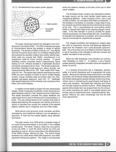
13.7.2 Omnidirectional holo diode cluster (typical) where the patterns intersect at the lens of the eye or other visual receptor.
14 · Auxiliary Spacecraft Systems
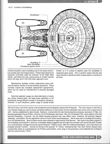
14.2.1 Location of shuttlebays
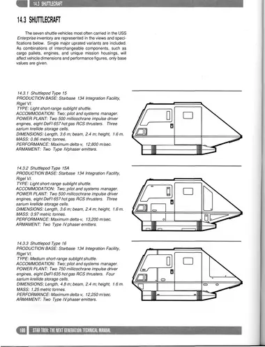
14.3.1 Shuttlepod Type 15 PRODUCTION BASE: Starbase 134 Integration Facility, Rigel VI.
14.3.2 Shuttlepod Type 15A PRODUCTION BASE: Starbase 134 Integration Facility, Rigel VI. TYPE: Light short-range sublight shuttle. ACCOMMODATION: Two; pilot and systems manager.
14.3.3 Shuttlepod Type 16 PRODUCTION BASE: Starbase 134 Integration Facility, Rigel VI.
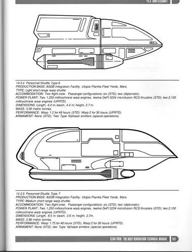
14.3.4 Personnel Shuttle Type 6 PRODUCTION BASE: ASDB Integration Facility, Utopia Planitia Fleet Yards, Mars. TYPE: Light short-range warp shuttle. ACCOMMODATION: Two flight crew. Passenger configurations: six (STD); two (diplomatic).
14.3.5 Personnel Shuttle Type 7 PRODUCTION BASE: ASDB Integration Facility, Utopia Planitia Fleet Yards, Mars. TYPE: Medium short-range warp shuttle. ACCOMMODATION: Two flight crew. Passenger configurations: six (STD); two (diplomatic). POWER PLANT: Two 1,250 millicochrane warp engines, twelve DeFI 3234 microfusion RCS thrusters (STD); two 2,100 millicochrane warp engines (UPRTD). DIMENSIONS: Length, 8.5 m; beam, 3.6 m; height, 2.7m. MASS: 3.96 metric tonnes. PERFORMANCE: Warp 1.75 for 48 hours (STD); Warp 2 for 36 hours (UPRTD). ARMAMENT: None (STD); two Type Vphaser emitters (special operations).
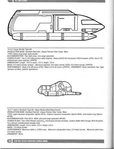
14.3.6 Cargo Shuttle Type 9A PRODUCTION BASE: Starfleet Plant #24, Utopia Pianitia Fleet Yards, Mars. TYPE: Heavy long-range warp shuttle. ACCOMMODATION: Two flight crew, one cargo specialist. POWER PLANT: Two 2,150 millicochrane warp engines, twelve DeFI2142 microfusion RCS thrusters (STD); two 2,175 millicochrane warp engines (UPRTD). DIMENSIONS: Length, 10.5 m; beam, 4.2 m; height, 3.6 m. MASS: 4.5 metric tonnes (empty). Maximum payload, 6.6 metric tonnes (STD); 8.9 metric tonnes (UPRTD). PERFORMANCE: Warp 2 for 36 hours (STD); Warp 2.2 for 32 hours (UPRTD). ARMAMENT: None (standard); two Type
14.3.7 Sphinx Workpod Type M1 (Base Module/Sled Attachments) PRODUCTION BASE: Starfleet Plant #2, Utopia Pianitia Fleet Yards, Mars.
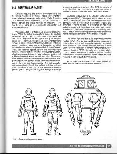
14.4.1 Extravehicular garment types
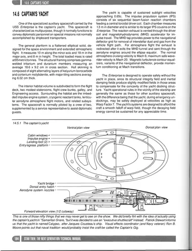
14.5.1 The captain's yacht
16 · Emergency Operations
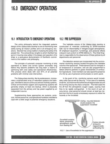
16.2.1 Use of forcefields for fire suppression
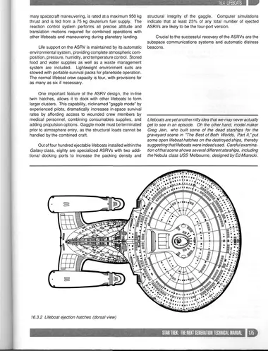
16.3.2 Lifeboat ejection hatches (dorsal view)
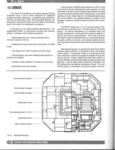
16.4.1 Typical lifeboat pod
17 · Conclusion
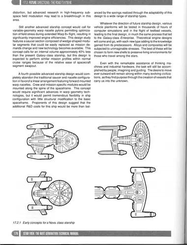
17.2.1 Early concepts for a Nova class starship