2.7 Saucer Module Separation Systems
Describes the docking latches, umbilicals, and procedures for separating the Saucer Module from the Battle Section, plus emergency landing of the saucer.
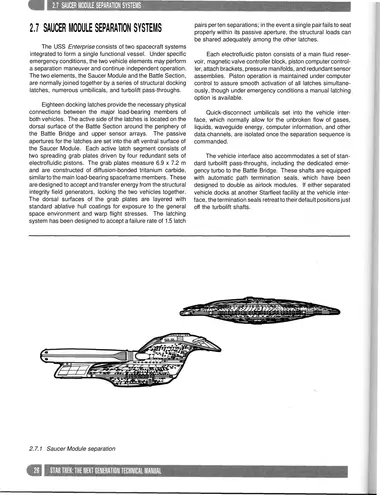
The USS Enterprise consists of two spacecraft systems integrated to form a single functional vessel. Under specific emergency conditions, the two vehicle elements may perform a separation maneuver and continue independent operation. The two elements, the Saucer Module and the Battle Section, are normally joined together by a series of structural docking latches, numerous umbilicals, and turbolift pass-throughs.
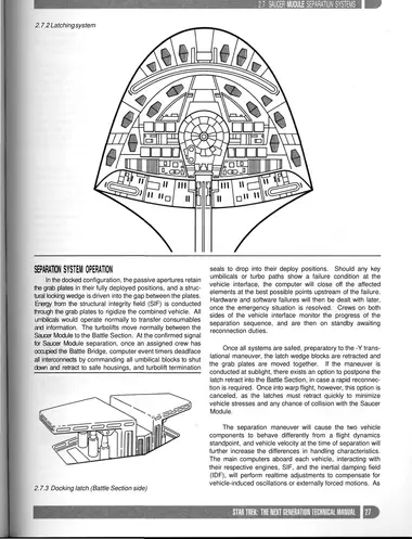
Eighteen docking latches provide the necessary physical connections between the major load-bearing members of both vehicles. The active side of the latches is located on the dorsal surface of the Battle Section around the periphery of the Battle Bridge and upper sensor arrays. The passive apertures for the latches are set into the aft ventral surface of the Saucer Module. Each active latch segment consists of two spreading grab plates driven by four redundant sets of electrofluidic pistons. The grab plates measure 6.9 x 7.2 m and are constructed of diffusion-bonded tritanium carbide, similar to the main load-bearing spaceframe members. These are designed to accept and transfer energy from the structural integrity field generators, locking the two vehicles together. The dorsal surfaces of the grab plates are layered with standard ablative hull coatings for exposure to the general space environment and warp flight stresses. The latching system has been designed to accept a failure rate of 1.5 latch pairs per ten separations; in the event a single pair fails to seat properly within its passive aperture, the structural loads can be shared adequately among the other latches.
Each electrofluidic piston consists of a main fluid reservoir, magnetic valve controller block, piston computer controller, attach brackets, pressure manifolds, and redundant sensor assemblies. Piston operation is maintained under computer control to assure smooth activation of all latches simultaneously, though under emergency conditions a manual latching option is available.
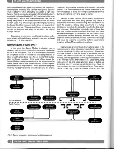
Quick-disconnect umbilicals set into the vehicle interface, which normally allow for the unbroken flow of gases, liquids, waveguide energy, computer information, and other data channels, are isolated once the separation sequence is commanded.
The vehicle interface also accommodates a set of standard turbolift pass-throughs, including the dedicated emergency turbo to the Battle Bridge. These shafts are equipped with automatic path termination seals, which have been designed to double as airlock modules. If either separated vehicle docks at another Starfleet facility at the vehicle interface, the termination seals retreat to their default positions just off the turbolift shafts.
Separation System Operation
In the docked configuration, the passive apertures retain the grab plates in their fully deployed positions, and a structural locking wedge is driven into the gap between the plates. Energy from the structural integrity field (SIF) is conducted through the grab plates to rigidize the combined vehicle. All umbilicals would operate normally to transfer consumables and information. The turbolifts move normally between the Saucer Module to the Battle Section. At the confirmed signal for Saucer Module separation, once an assigned crew has occupied the Battle Bridge, computer event timers deadface all interconnects by commanding all umbilical blocks to shut down and retract to safe housings, and turbolift termination seals to drop into their deploy positions. Should any key umbilicals or turbo paths show a failure condition at the vehicle interface, the computer will close off the affected elements at the best possible points upstream of the failure. Hardware and software failures will then be dealt with later, once the emergency situation is resolved. Crews on both sides of the vehicle interface monitor the progress of the separation sequence, and are then on standby awaiting reconnection duties.
Once all systems are safed, preparatory to the -Y translational maneuver, the latch wedge blocks are retracted and the grab plates are moved together. If the maneuver is conducted at sublight, there exists an option to postpone the latch retract into the Battle Section, in case a rapid reconnection is required. Once into warp flight, however, this option is canceled, as the latches must retract quickly to minimize vehicle stresses and any chance of collision with the Saucer Module.
The separation maneuver will cause the two vehicle components to behave differently from a flight dynamics standpoint, and vehicle velocity at the time of separation will further increase the differences in handling characteristics. The main computers aboard each vehicle, interacting with their respective engines, SIF, and the inertial damping field (IDF), will perform realtime adjustments to compensate for vehicle-induced oscillations or externally forced motions. As the Saucer Module is equipped only with impulse propulsion, computational modeling has verified that special cautions must be observed when attempting separation at high warp factors. Prior to leaving the protection of the Battle Section's warp field, the Saucer Module SIF, IDF, and shield grid are run at high output, and its four forward deflectors take over to sweep away debris in the absence of the dish on the Battle Section (See: 7.4). Decaying warp field energy surrounding the Saucer Module is managed by the driver coil segments of the impulse engines. This energy will take, on average, two minutes to dissipate and bring the vehicle to its original sublight velocity.
Discussions of emergency conditions and actions on the parts of both vehicles following separation can also be found in Sections 11.5, 11.6, and 15.8.
Emergency Landing of Saucer Module
In the event the Saucer Module is disabled near a planetary body and cannot maintain a stable orbit, landing the saucer is the final option. This is to be attempted only when an acceptable chance of success has been computed and all other available procedures have failed, short of total evacuation by lifeboat modules. If the senior officer aboard the Saucer Module makes the decision that the attempt must be made, special sets of crew procedures and stored computer commands will be implemented. While extensive computer modeling has been taken into account in creating the landing programs, no guarantee as to their effectiveness can yet be offered. SIF reinforcement of the saucer framework is believed necessary to avoid exceeding saucer structural limits during atmospheric entry of a Class M planet.
Without at least minimal reinforcement, aerodynamic loads associated with most entry profiles may result in spaceframe destruction prior to landing. As it was deemed too costly to subject a Galaxy class spaceframe to a full-up atmosphere entry test, the computer model is the best available reference. Starfleet has recorded a total of three data sets from previous smaller starship hull landings, and these were extremely helpful in the design of the computer routines. Conventional wisdom believes, however, that the Galaxy class hull is still outside the survivable performance envelope and would be unable to successfully perform a deorbit and entry into a Class M compatible atmosphere.
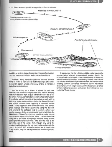
A complex set of terrain touchdown options reside in the main computers, taking into account such factors as contact material, air density, humidity, and temperature. If there is an adequate amount of time for sensor scans during the approach, the sensor values will be compared to those in memory, and the appropriate control adjustments can be sent to the impulse engines and field devices. Beach sand, deep water, smooth ice, and grassy plains on Class M bodies are preferable sites; in contrast, certain terrain types have not been modeled, such as mountainous surfaces. Other nonterrestrial bodies may possess survivable surfaces, and their suitability as landing sites will depend on the specific situation, computer recommendations, and command decisions.
Naturally, many planetary types will possess environments so hostile to crew survival that remaining in orbit will be a preferable option, unless emergency landing is mandated by tactical considerations.
Prior to landing on a Class M planet (as only one example), the structural integrity field and inertial damping field would be set to high output, with the SIF also set to flex the vehicle in small, controlled amounts for shock attenuation. The deflector grid will be set to a high output as well, with its field decay radius configured to optimize the Saucer Module's final slideout distance while applying a controlled friction effect. During approach the computer would take atmospheric readings and make adjustments along the descent, and command the deflector field to perform airflow and steering changes. In the event computer control is limited, the Flight Control Officer (Conn) should be able to make manual attitude control inputs from his/her panel. The IDF would be configured to "jolt mode" during major impacts, if they exceed certain preset translational limits. The deflector field is designed to protect the vehicle hull, though only up to the specified load limits when the hull must make contact with the ground. If the SIF, IDF, and deflector grid are all functioning during slideout, they can add a great deal to minimizing impact forces.
It is assumed that the vehicle would be a total loss insofar as ever being returned to operational service, due to the extreme loads placed upon it, which would result in deep, unrecoverable alloy damage. Postlanding mission rules call for full security measures to protect the crew and vehicle while awaiting Starfleet assistance. Numerous options have been documented, from simple waiting within Federation or allied territory, to total evacuation and vehicle destruct in areas controlled by Threat forces.